Power Distribution Box

From Idea To Product

On a typical sound-cart for motion-picture and TV filmmaking there are lots of devices that require something around 11–14V DC. The recorder, mixer, wireless microphone receivers and maybe a light all need this kind of power. So it is pretty handy if they all can be powered from a single big rechargeable Li-Ion battery. For this purpose I built a power distribution box that connects all these devices to one power source and that has individual switches for all of them so the ones not in use can be powered off easily.

Feature-List

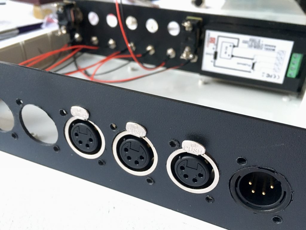
  • 4-pin XLR connections
  • one input
  • seven outputs
  • seven on/off switches
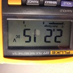
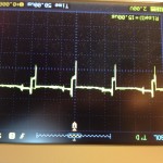
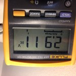
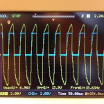
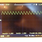
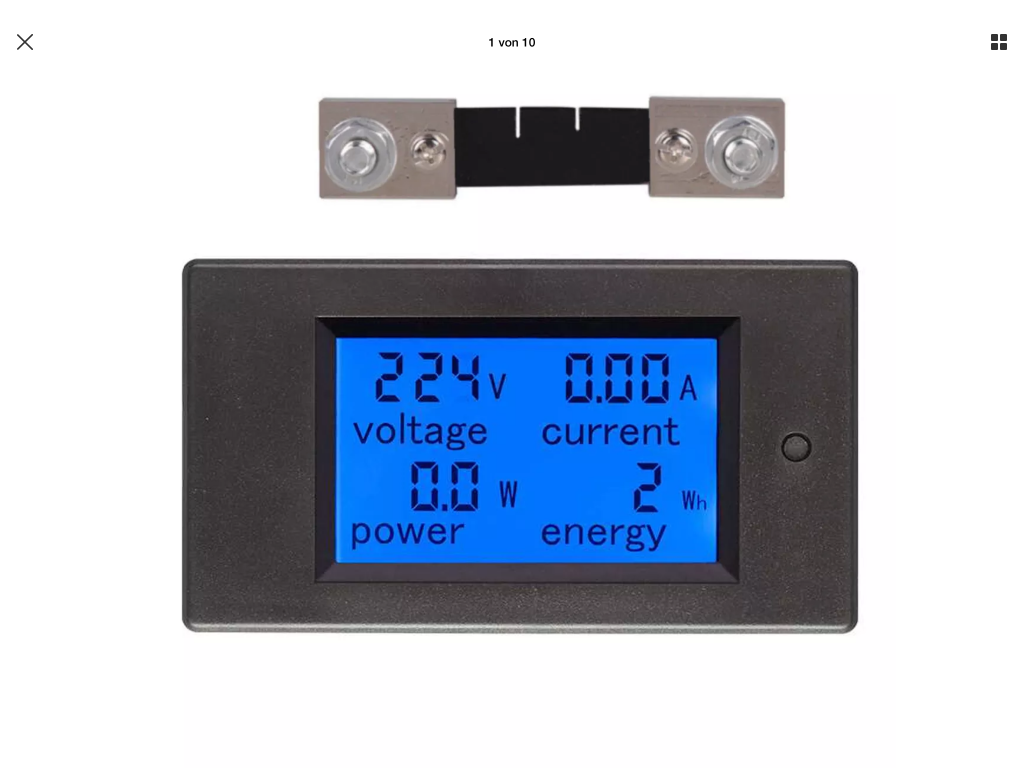
  • LCD for voltage, current and power consumption metering
  • self-resetting fuses on every output
  • solid plastic or aluminum housing
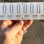
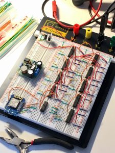
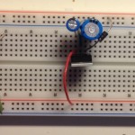
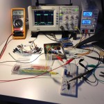
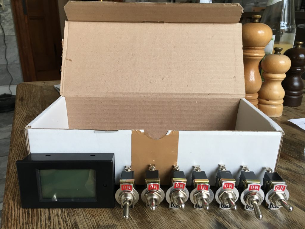
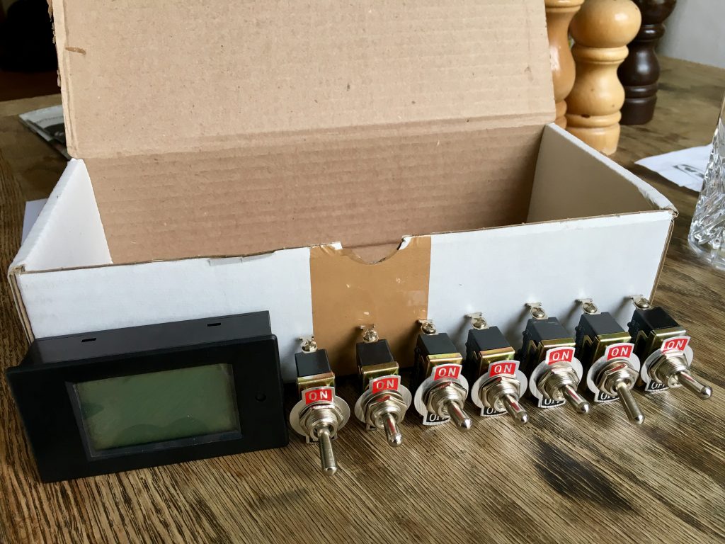
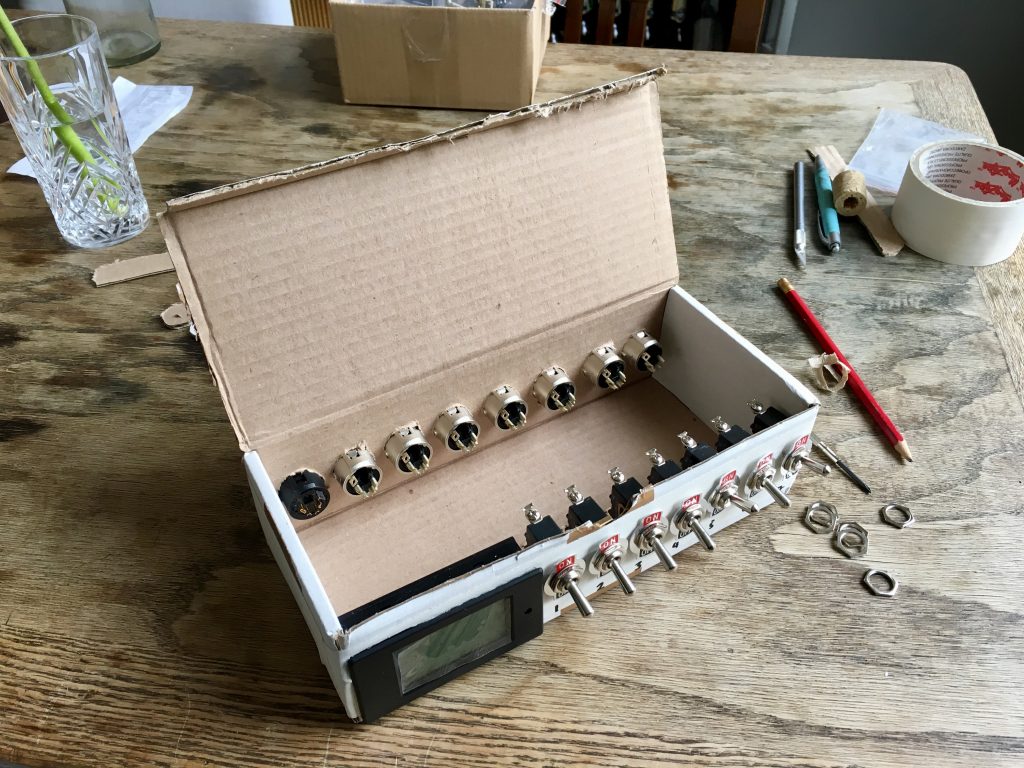
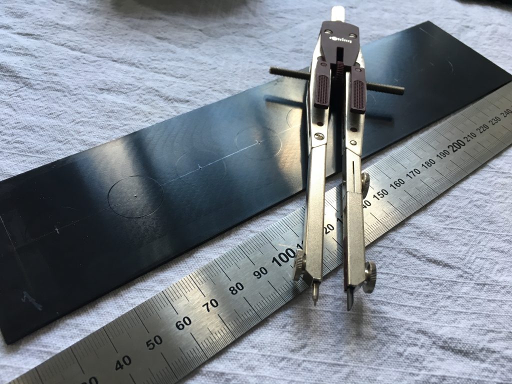
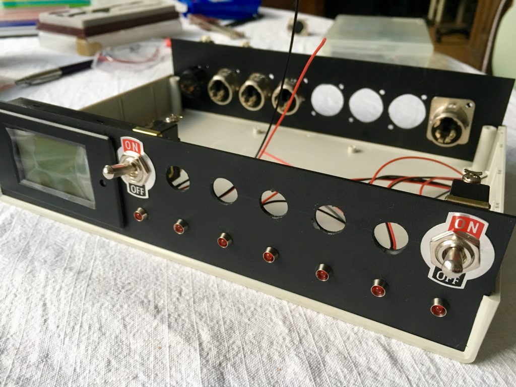
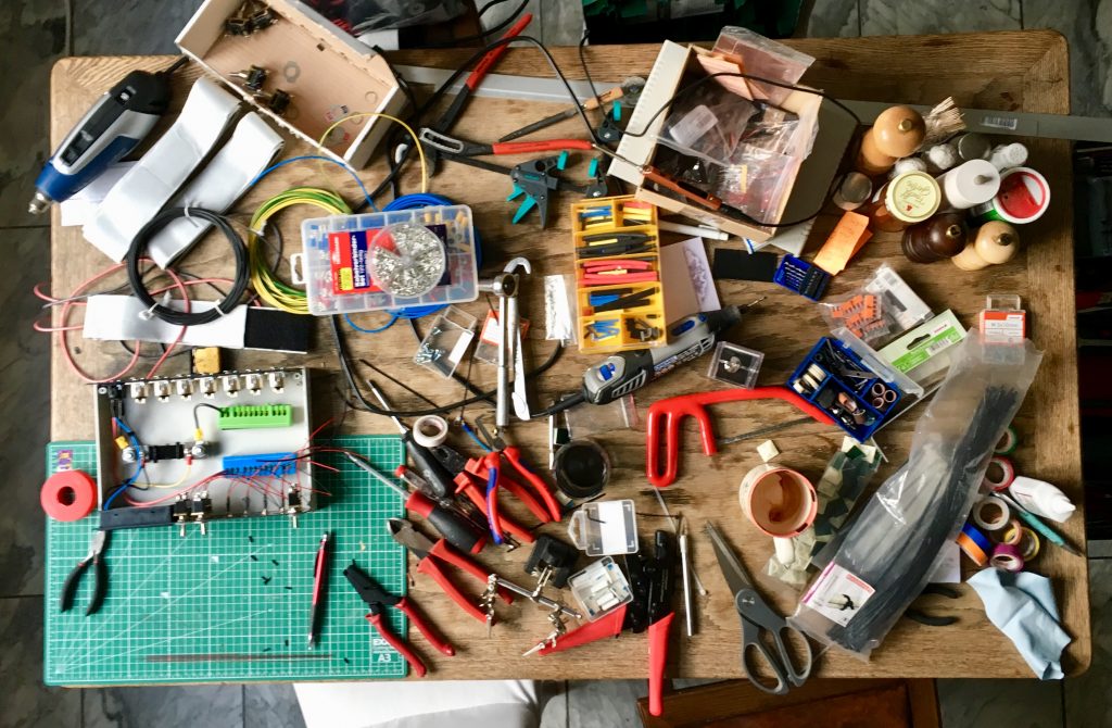
Prototype

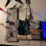
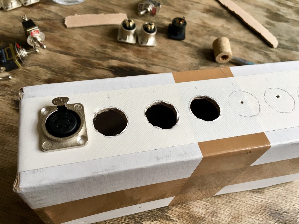
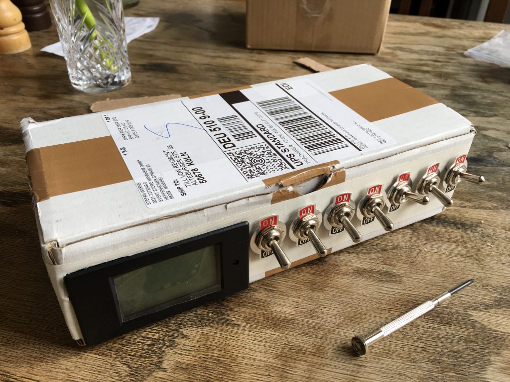
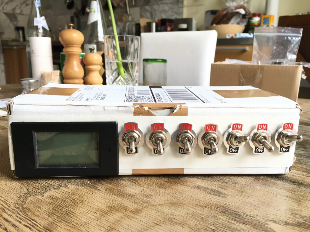
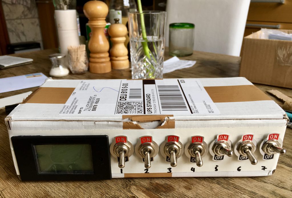
I started out with an empty cardboard box I had lying around. To see if all the switches and the LC display fitted the space it provided I made a kind of prototype.
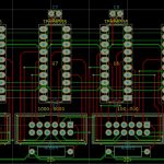
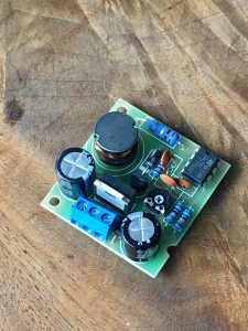
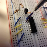
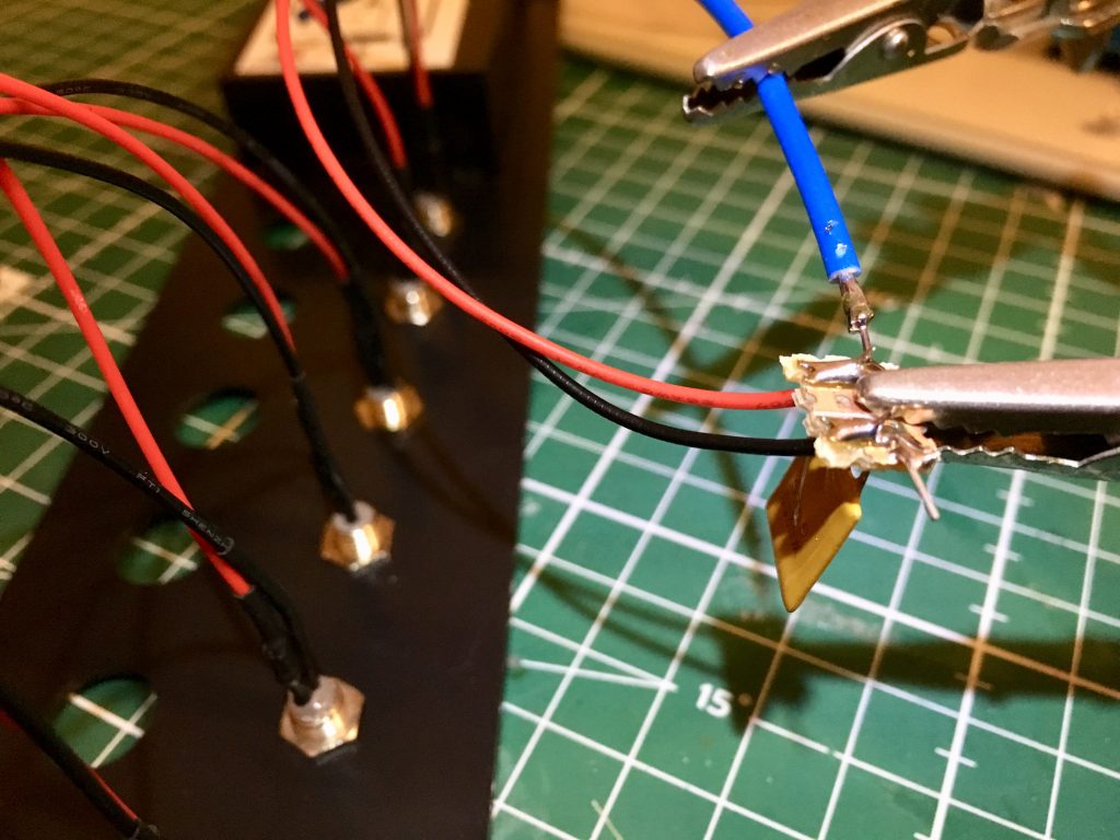
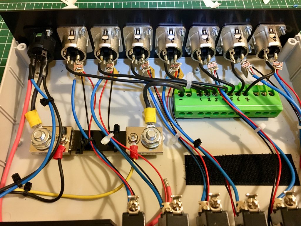
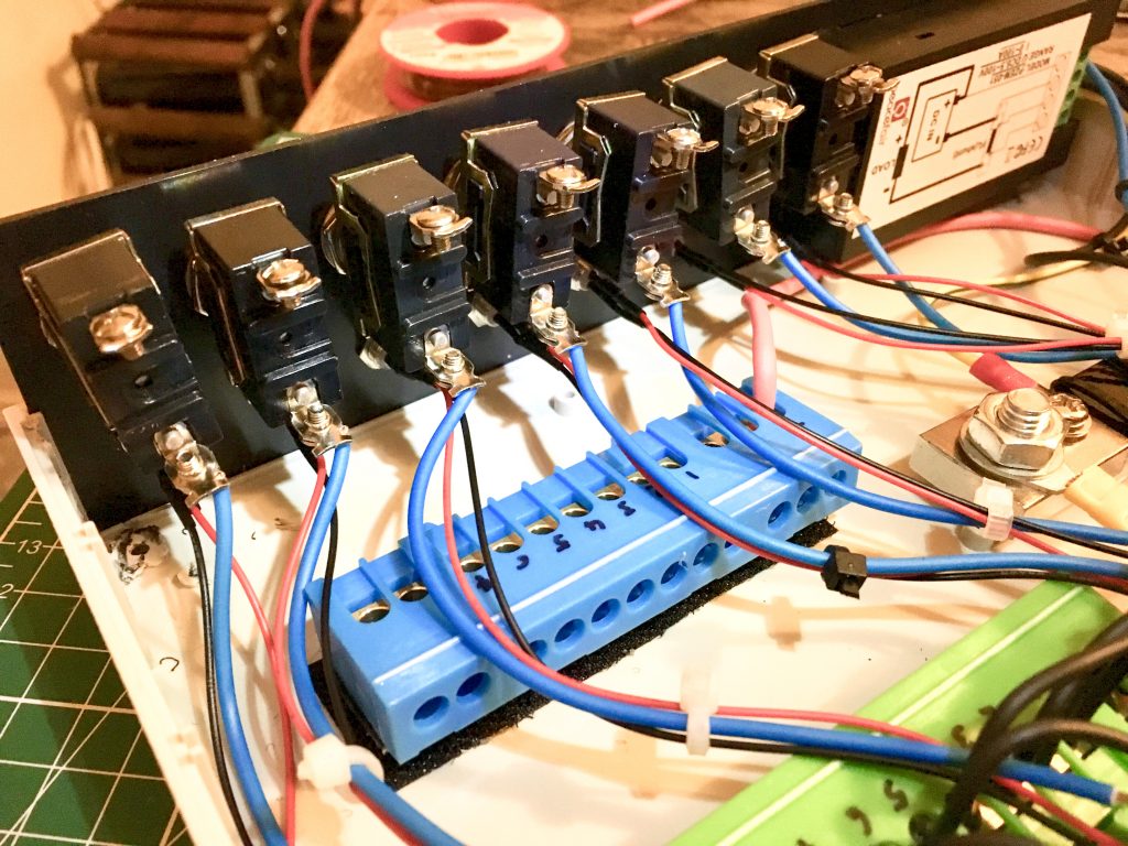
Fuses

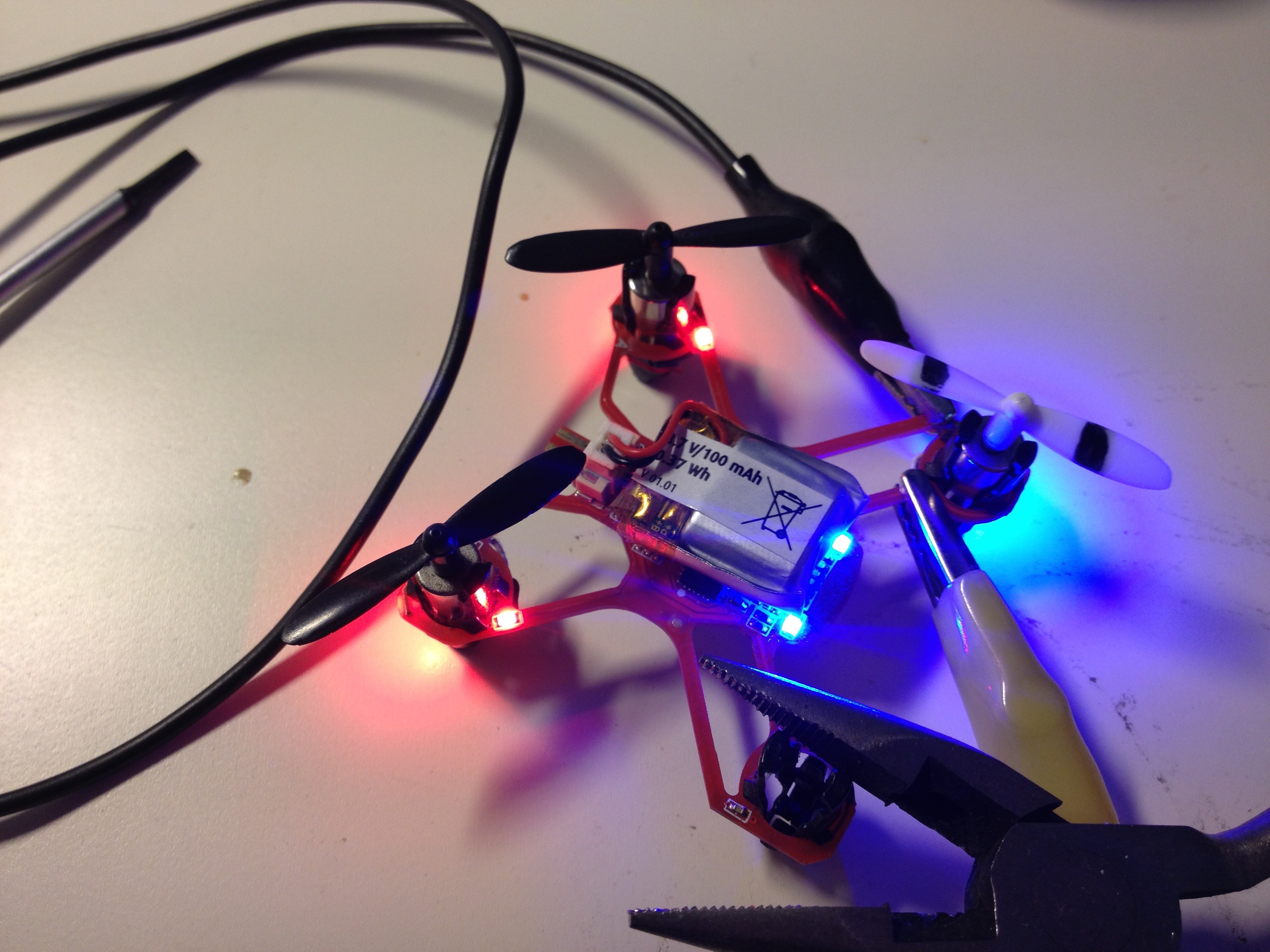
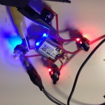
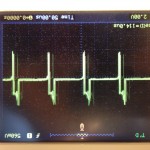
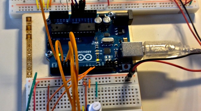
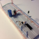
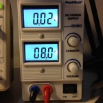
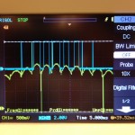
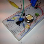
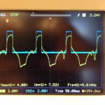
Now I knew how much space I needed to fit all the parts. I had never before worked with self-resetting PTC polyfuses so I experimented around a little bit.

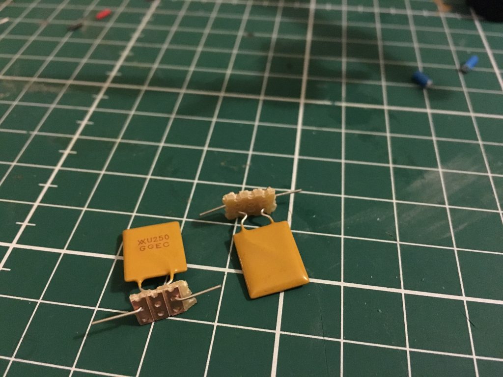
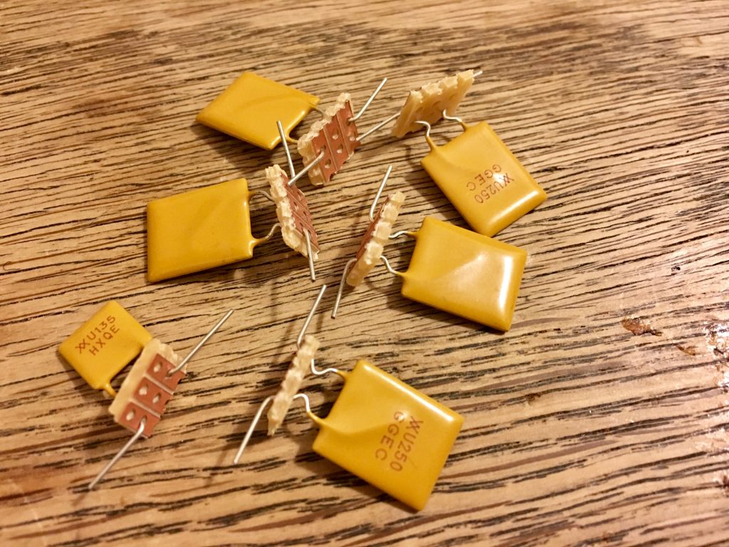
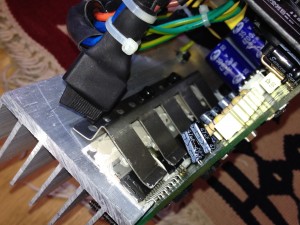
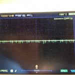
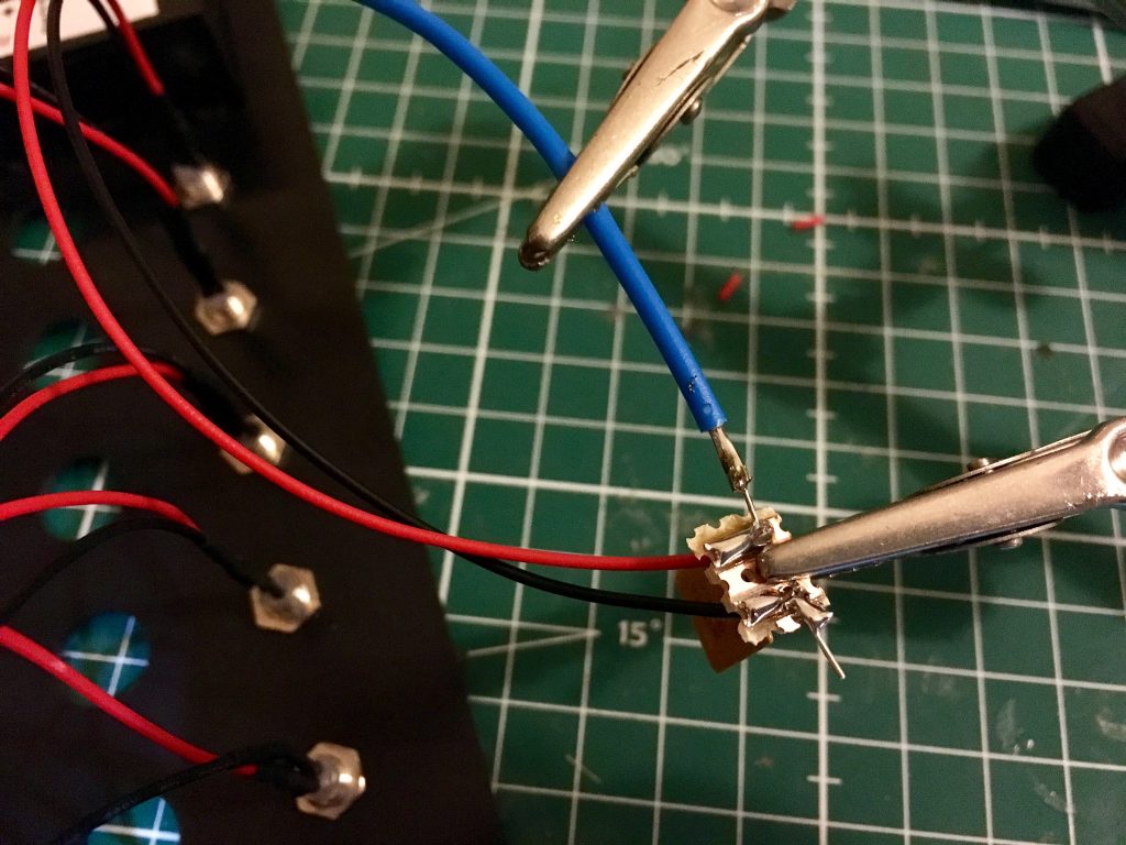
I also thought it would be nice to have an LED light up whenever one of those fuses goes off. So I soldered a tiny circuit board to each output socket that connects the output, the fuse and the LED. The LED actually bridges the fuse. That means: when the fuse goes off (meaning it becomes non-conductive) all the voltage is dropped across the LED and its built-in resistor so it lights up.
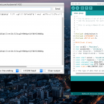
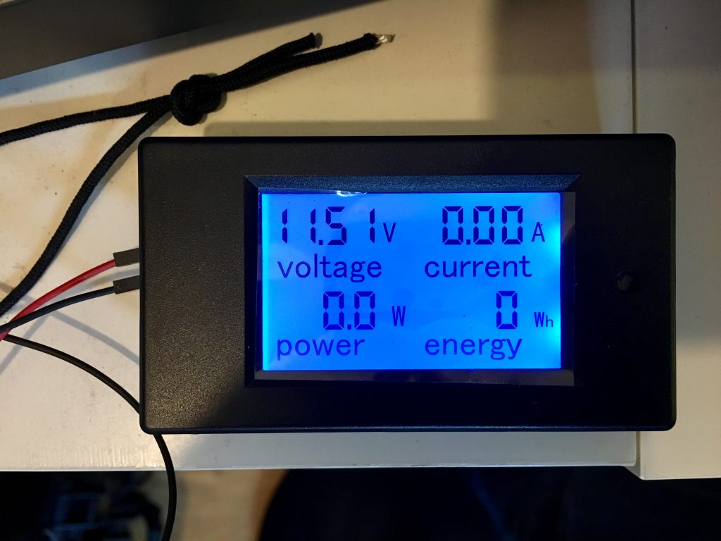
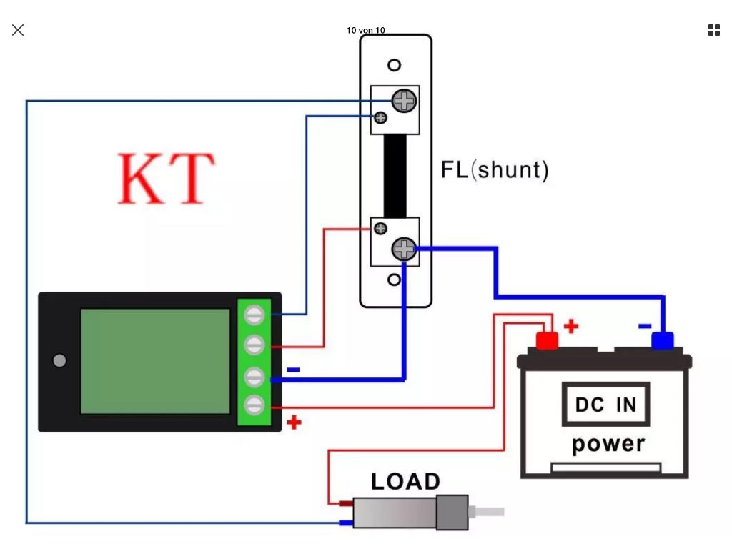
LCD

The LCD I used was bought as-is off eBay and it came with a wiring diagram which I had to implement into my build.
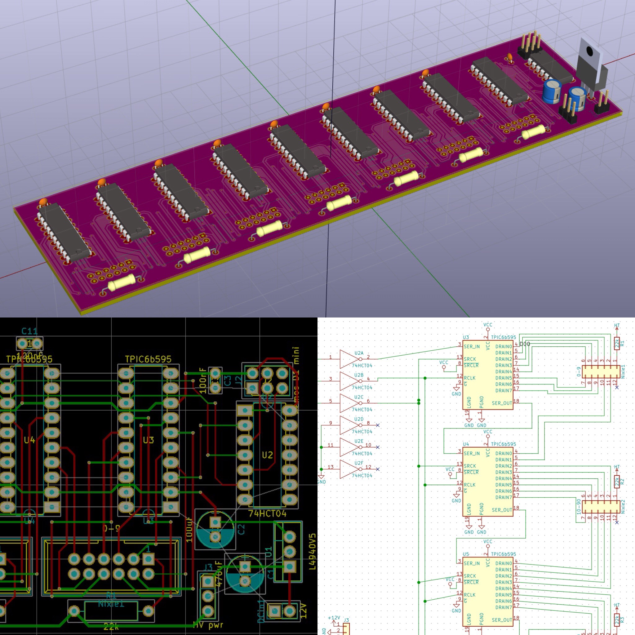
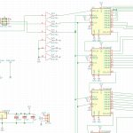
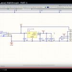
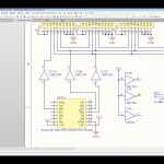
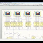
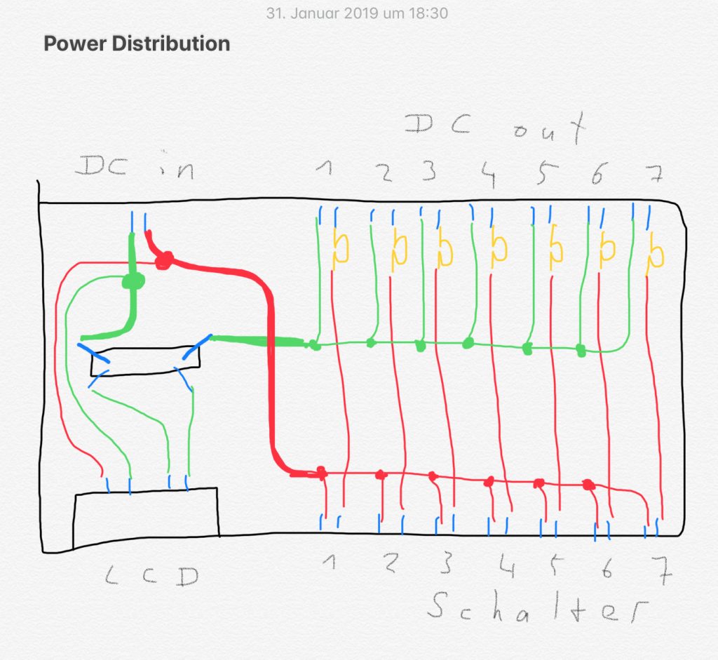
Schematic

So this is the schematic for the whole box. Notice the LEDs are missing in this. the go across the yellow ohm symbols.
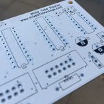
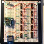
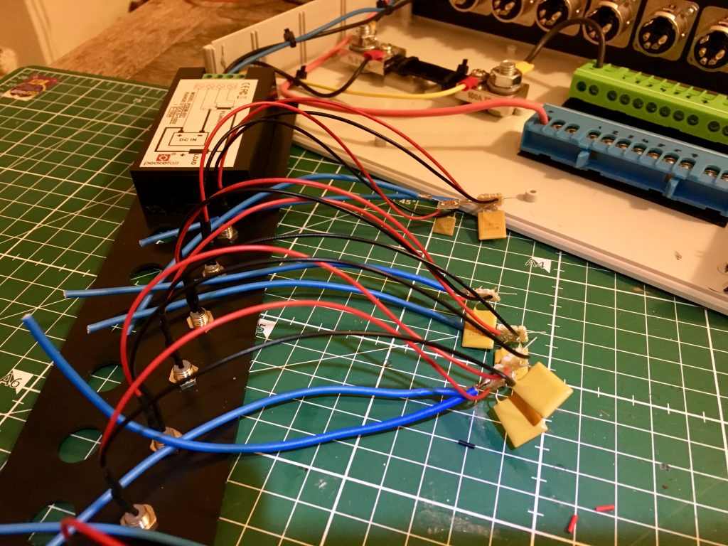
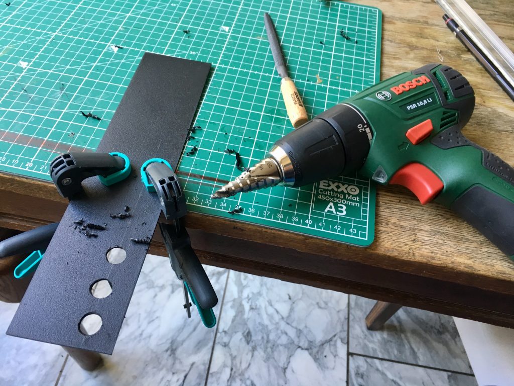
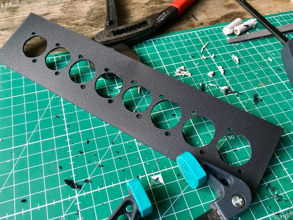
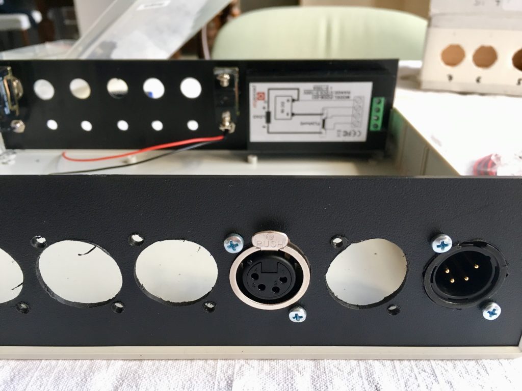
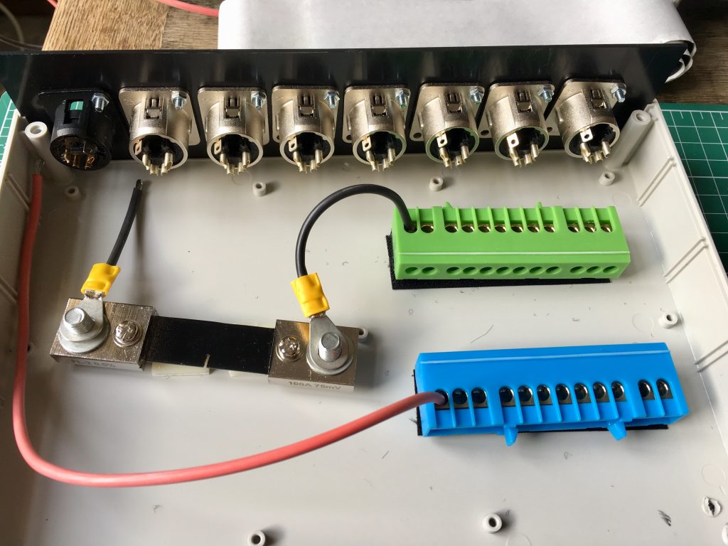
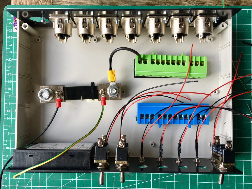
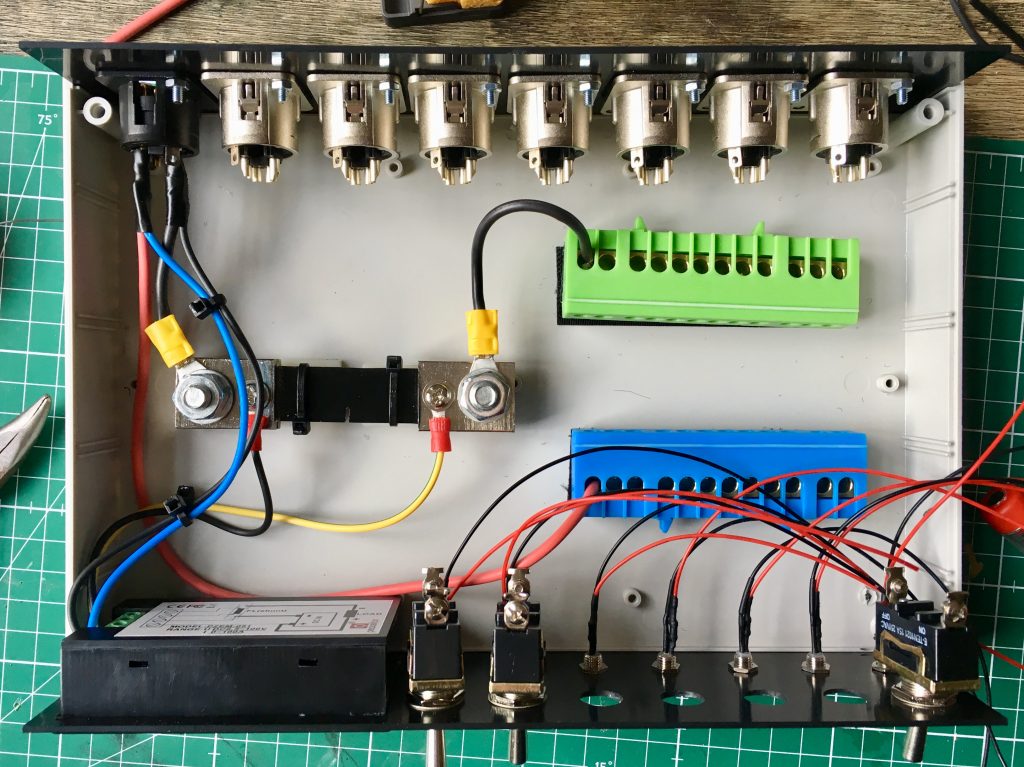
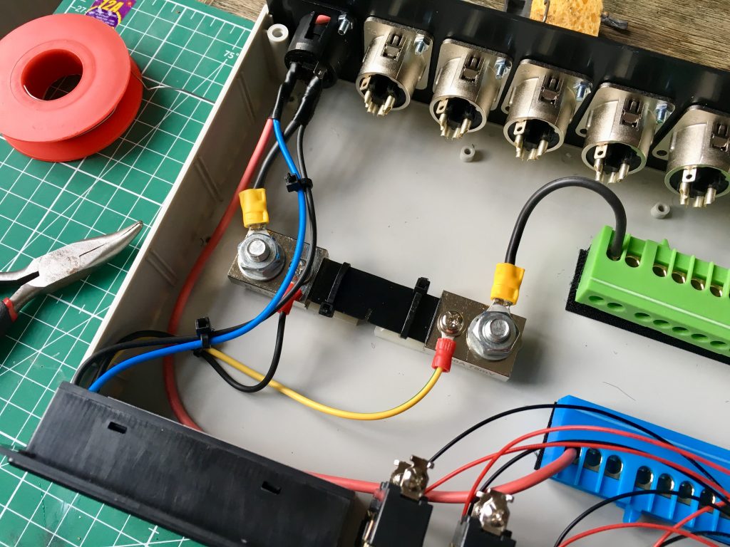
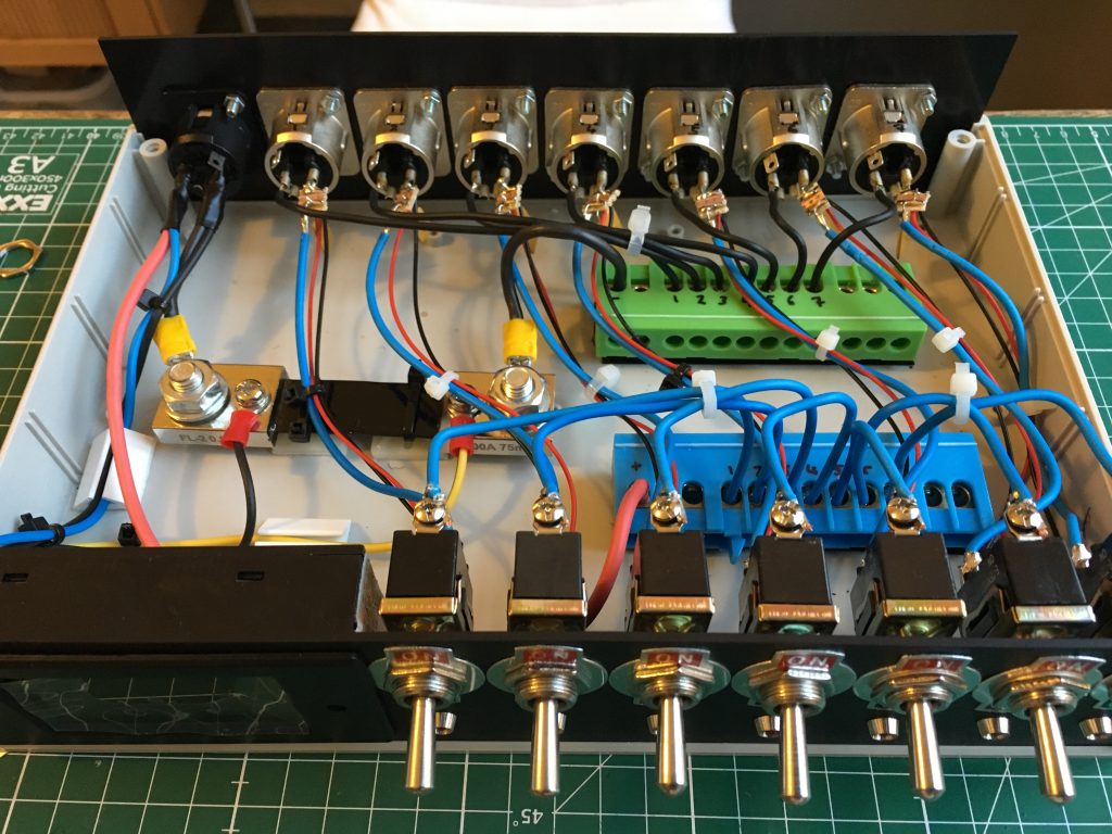
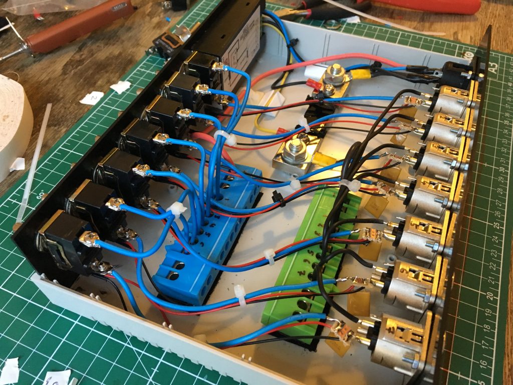
The Build

After ordering a plastic housing of the correct size I went to work and started putting it all together as best I could.
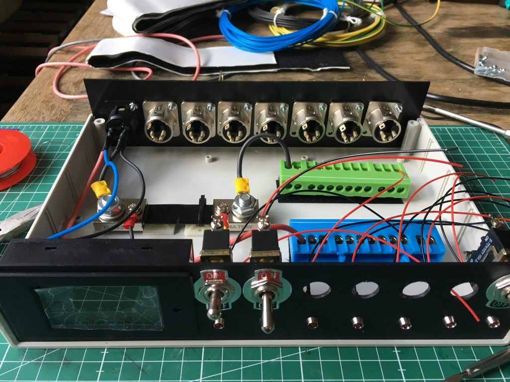
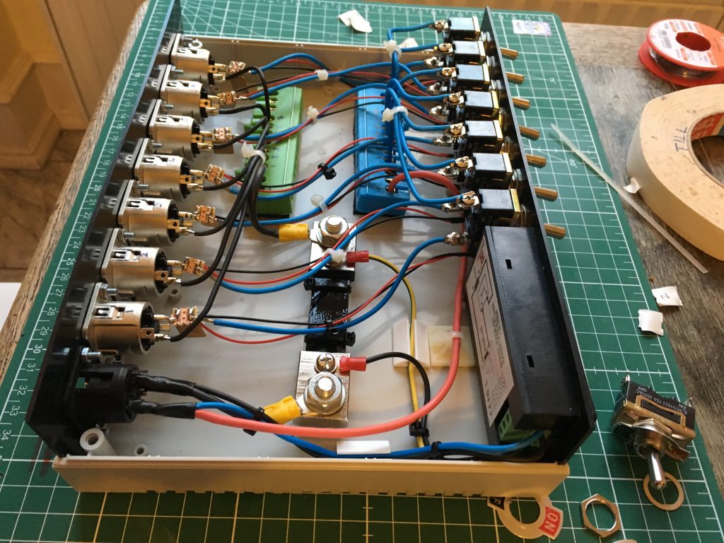
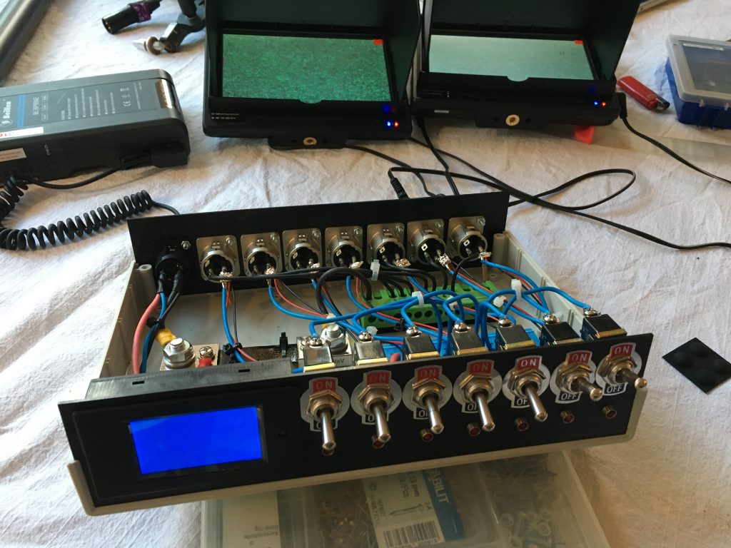
Finished

The result came out quite nice, I think.

power box
power box on the top left of this sound cart

Nixie Display (6): On The Wall!

[other parts of this series]

It is done! The final version of the hardware sits on my living room wall in a nice wooden frame. The software works, too! Apart from the fact that SoundCloud don’t give out new API keys to developers of apps everything works perfectly. It just means that I have to search for a new random API key myself and save it to my Arduino Programm running on the WeMos. Also I had to tweak the php script running on my webserver. Remember that the Arduino gets the actual number to display from this php script because it doesn’t have sufficient memory to calculate it on-board. So php does the “heavy lifting” for it. SoundCloud API has some wonderful quirks to work around. The list of tracks it returns for a given user has 50 entries max. If a user has more tracks, you must use a paginated variant of the API call. This way you get multiple answers. But: in the chunks of 50 tracks some of the tracks can occur in two different chunks. So you have to check if you encountered a given track ID before, and only if not save that track’s play_count.

Download the php and Arduino files:

Still there remains a discrepancy between the plays my script calculates and the plays shown in the official SoundCloud “Pulse” App. This is due in to some hidden (non-public but scheduled for release) tracks that have a few plays which are not returned by the API call.

Hurra!, all is good now:

See it in action!

Nixie Display (5): Schematics and PCBs in KiCAD

[other parts of this series]

After the breadboard version of the circuit was proven to be functional and the software I came up with was working I decided to use KiCAD to make useful schematics and design my own PCB that I can use in my Nixie Tube SoundCloud Play-Counter project. There is a really useful Tutorial in the help menu of KiCAD and on their website that got me started with this lovely open source program that runs on Windows, Mac and Linux and has no limitations on maximum board sizes etc. like a lot of the free versions of big paid software do. Since I am working on an Apple Macintosh I also shortly considered using Eagle, but since I didn’t want to buy the software that choice would have limited me to a half-size euro board. Altium Designer, PADS (PowerPCB), ORCAD and Allegro as well as CircuitMaker or CircuitStudio are all Windows-only options so I didn’t look at them.

You can download my KiCAD files and use them if you want.

Following some YouTube tutorials and more online documentation I generated the Gerber files that are necessary for ordering an actual manufactured PCB. After checking out some services like Osh Park, Seeed Studio and Elecrow I decided to try

Pcbway

and ordered there. I like the way they have the ordering process set up and it seems to me they’re really fast and also pretty cheap. I went ahead and placed an order of the minimum quantity of five boards.

After soldering all the parts to the board I went ahead and plugged everything in: the external 12V power supply, the Wemos D1 mini, the 160V power supply board and finally all seven nixies. It was a really cool moment switching on power for the first time! All works fine! No parts heat up, no shorts! The entire circuit uses 27.5 to 220.0mA, averaging to a mere 155mA over time says my Fluke 177.

Nixie Display (2): APIs and Parts

[other parts of this series]

The first thing I did was go on eBay and buy twelve cheap Nixie IN-12A tubes. They don’t have the decimal point like the IN-12B but I don’t need it.

Then I watched Dave’s EEVBlog videos again quite a few times and I was able to screen capture his schematics for the electronic layout. The whole system relies on a Wemos D1 mini. This is a micro controller with built-in WiFi than can be programmed using the Arduino software on you computer. To actually switch on the Nixies which require 160V Dave found some really cheap shift registers called TPIC6B595 that can handle the high voltages.

Next I bought a high voltage power supply on eBay. It was a set containing a little PCB, all the components and a manual. I had some breadboards and jumper wires still lying around at home.

While I waited for all the goodie to arrive I fired up the Arduino software on my laptop and began programming the Wemos D1 mini. The sad thing was that I couldn’t find the code that Dave had written for his own project so I was stuck having to come up with my own code. I am NOT good at this so it took me quite a while to understand what I had to do. And I’m still not done yet. But I have made some really good progress.

My research involved getting to know the SoundCloud API and learning how to get to the numbers that I need through it. Since there’s no way to ask for the total play count of a given user, I had to parse an answer that is in the JSON format that holds a huge list of all of a user’s tracks including descriptions, keywords and everything else. I had to find the number of plays for every single track in this huge mess of characters. To do this with Arduino, I installed the famous Arduino JSON library and looked at the example code they provide with it. It took me a while to figure out that the SRAM memory of the tiny micro controller I use is way too small to hold that entire string. So I failed searching or parsing the string for the entries I needed.

My brother came up with an idea for a solution to this: write a PHP script for your WordPress server, then you give it the SoundCloud user ID and your own secret API ID key handle and it returns the total number of plays! Yay! For a big server computer the parsing of a huge JSON string is no problem. And the tiny answer that it gives can be parsed by the Arduino running on the Wemos D1 mini.

Download the PHP script or try it out at
http://mixedtinkerings.com/tillefon/calcscplays.php?SCUserID=0&SCApiClientID=JlZIsxg2hY5WnBgtn3jfS0UYCl0K8DOg

The Arduino sketch I have so far logs into my WiFi, reads the answer that my PHP script gives and prints it on the serial monitor. I am sooo happy!

Download Arduino sketch here to look at it!

As soon as my shift registers arrived, I started to place them on my breadboards. I don’t want to connect the hight voltage yet and that’s why my next step will be using LEDs instead of all the segments of the tubes to try out if my software works. Since my software is not finished yet, I stopped putting stuff together on the breadboard so I can focus on getting the numbers out of the computer chip into the real world!

Syncing Video and Audio using Tentacles

Testing Tentacles to synchronize via Timecode the video files of my Canon 5D Mark III DSLR to the sound files of my Tascam HD-P2 audio recorder. The camera doesn’t have a TC input, so I record it to the mic input on one of the camera’s audio tracks. The HD-P2 however has a real TC input so I set it to slave to the external TC. In Final Cut Pro the two clips couldn’t be made to match, no matter what I tried. Using the Tentacle Sync software supplied with their hardware however it was really quick to export a perfect clip!

Load the Tentacle Software at Tentacle’s Homepage and have a go with my two original files that you can download here:

[download_link link=”http://mixedtinkerings.com/wp-content/uploads/2016/04/BWF-05.wav”]Audio File[/download_link]

[download_link link=”http://mixedtinkerings.com/wp-content/uploads/2016/04/E87A1546.MOV”]Video File[/download_link]

Dead Woofer in Opera Active PA Speaker

The other day I got my two Opera Live 210 active PA speakers out and I noticed that in one of them only the tweeter was working. Oh no! So I decided to take it apart since it is way too old to be eligible for warranty. I was really surprised how well designed they are! Everything is neat and clean and almost as if they are made to be taken apart. What I found though was’nt that cool: I measured resistance of the speaker coil in the woofer with my multimeter and got an incredibly low .6Ω. Well I guess that means that it is practically shortened, probably in an overload situation. That’s very strange since these speakers are active and have a built-in overload-protection-circuit. I guess it didn’t work so well. ;-( To see if the part of the active amplifier that drives this speaker still works I hooked up my multimeter to its outputs without the woofer being connected. Turning the volume up or down didn’t change the displayed 0V. My guess is that this means that the short in the woofer also killed the amp in the process. That’s really too bad, because I really liked these speakers. They are no longer manufactured.

One funny thing I also found is that some screws had come loose over the years. They are used to mount the OpAmps to a cooling brick. One of those three screws had vanished so I looked around inside the case and I found it: it was clinging to the speaker’s magnet!

Listen to the awful sound of only a tweeter. I recorded the speaker before taking it apart:

Tiny nano Quad on the Oscilloscope

Just out of fun I hooked my tiny little Revell Mini Quad Copter Nano Quad up to the oscilloscope to see at what voltage these little motors are operated. The are obviously driven by a pulse modulated signal of 3.2V peak-to-peak (or whatever the battery can deliver). The pictures show throttle of 0, half and full:

first dynacho pics